| Item | Description | Points of Interest for Inspection |
| 1 | Trolley rail bolted splices. | Loose and missing splice bolts, check for improper hardware. Joint bar bolts have straight shanks to the head and are made per ASTM A449. Nuts are per A563 grade B. A325 bolts and nuts may also be used. Check/tighten splice bolts every 3 months. Fasteners should include a helical spring lock washer per AREA specification. |
| 2 | Trolley rail clamps or clips. | Check for fractured clamps, cracked welds, loose and broken bolts. |
| 3 | Trolley rail: erosion under rail base | Under the base of the rail, check for erosion of the girder flange or the wear plate (if present). |
| 4 | Trolley rail support. | Check for top flange cracking at the edge of the rail base. Check for tack welds at the edge of the rail base. |
| 5 | Trolley rail elevations. | From one end of the trolley rail, sight down the rail head. Sight over the entire length of the rail for dips in elevation. Check for local deformation of the girder flange that supports the rail. “Dishing” or dips in the girder flange may indicate broken intermediate diaphragms or broken welds. Check this condition at both trolley rails. See Figure 7‐1. |
| 6 | Girder camber. | Position the trolley at the extreme end of the bridge. From the end of the bridge opposite the trolley, position your line of sight to be in‐line with one of the trolley rails, and nearly at the same elevation as the rail head. The elevation of the rail near the middle of the bridge span should be visibly higher than near the ends (positive camber). If conditions do not permit this observation, or if positive camber is not observed, detailed measurements are required. Repeat the procedure for the other trolley rail. |
| 7 | Torsion‐box rail support. | For box girders that support the trolley rail directly over the inside web plate, check for cracking of the girder flange‐to‐web weld. |
| 8 | Trolley end stops. | Welds, base metal, and attachment to girder. Confirm that trolley bumpers make simultaneous contact with the end stops at both ends of trolley travel. |
| 9 | Bridge drive mounting bases | Check the condition of girder web where bridge machinery is attached. Look for out of plane deformation of the girder web or cracking of the material adjacent to where bars are welded. S |
| 10 | Line shaft bearing supports. | Check the condition of girder web where bearing supports are attached. Look for out of plane deformation of the girder web or cracking of the material adjacent to where bars are welded. |
| 11 | Platform connections to girder. | Check the condition of girder web where platform support gusset plates are attached. Look for out of plane deformation of the girder web or cracking of the material adjacent to gusset attachments. |
| 12 | Festoon/span conductor supports. | Check the condition of girder web where conductor supports are attached. Look for out of plane deformation of the girder web or cracking of the material adjacent to where gussets or bars are welded. |
| 13 | Pendant festoon supports. | Check support members, welded and bolted connections. |
| 14 | Riveted girders. | Inspect riveted construction |
| 15 | Girder welds. | Longitudinal flange‐to‐web welds. Inspect the location of shop splices for web and flange plates |
| 16 | Girder lower flange and web. | Inside edges of the bottom flanges, including the adjacent web area for damage due to wire rope abrasion, impact from load blocks, or lifting beams. For cranes with lifting beams, also check the condition of the bottom surface of the bottom flange for impact from two‐blocking accidents. If rope guards are present, inspect the rope guard attachments to the girder. |
| 17 | Walk‐in girders. | Welds and base metal for intermediate and full depth diaphragms, girder webs, girder flanges. |
| 18 | Bolted girder splices. | Check bolts in top and bottom flange splices and web splices . |
| 19 | Girder connection notch. | See Figure 7.6. Check welds and base metal at corners and where welds meet at corners. Check welds where girder webs are welded to horizontal shelf plate. |
| 20 | Equalizer saddles. | See Figure 7‐7. Check welds and base metal where the vertical saddle plates are welded to the horizontal saddle plate. Also check welded connections to girder. |
| 21 | Platform truss. | Welds and base metal for all truss members and gusset plates. See Figure 7‐4. |
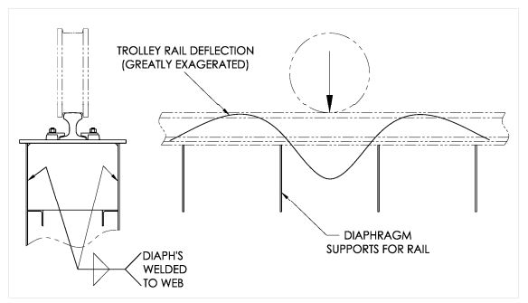
Figure 7‐1
Schematic illustration of how the trolley rail deflects. The upward force produced by
leverage from the trolley wheel is resisted by the rail clips or clamps.
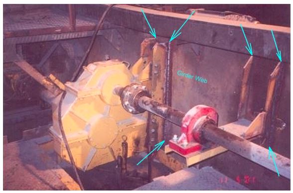
Figure 7‐2
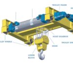
Bridge machinery supports.
Check girder web and welds for vertical bars to web.

Figure 7‐3
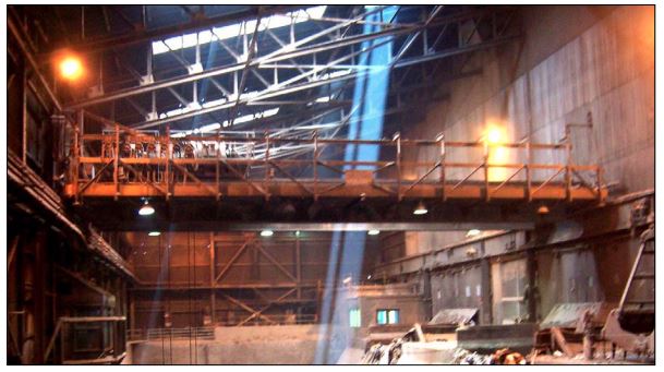
Crane with an outrigger truss. The diagonal members are part of the truss that supports the
platform, bridge machinery, and festoon track.
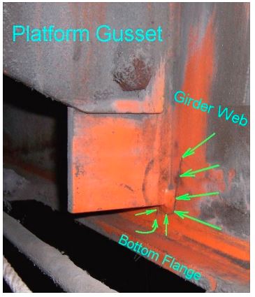
Figure 7‐4
The girder web is cracked at
the toe of the fillet weld for
platform connection bar.
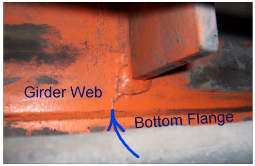
Figure 7‐5
This is a close‐up view of Figure 7‐4. The arrow points to the end of the crack. The crack is
propagating toward the bottom flange of the girder. Cracks in the bottom flange of a girder
can cause a catastrophic girder failure.
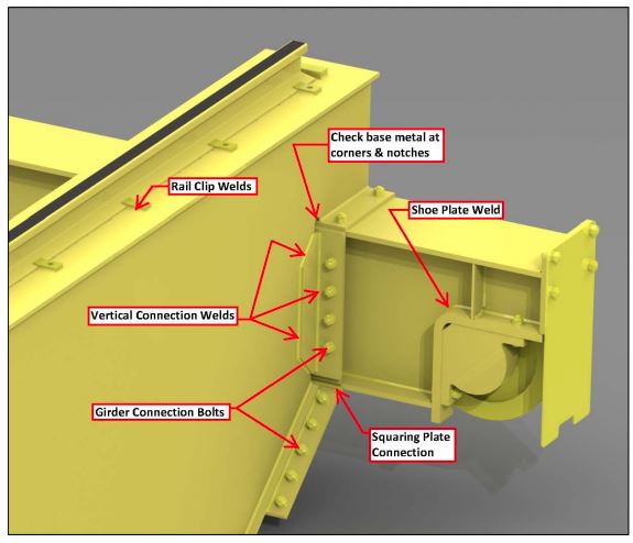
Figure 7‐6
Girder End Connection
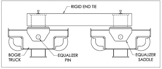
Figure 7‐7
Equalized bogie trucks with rigid end tie