

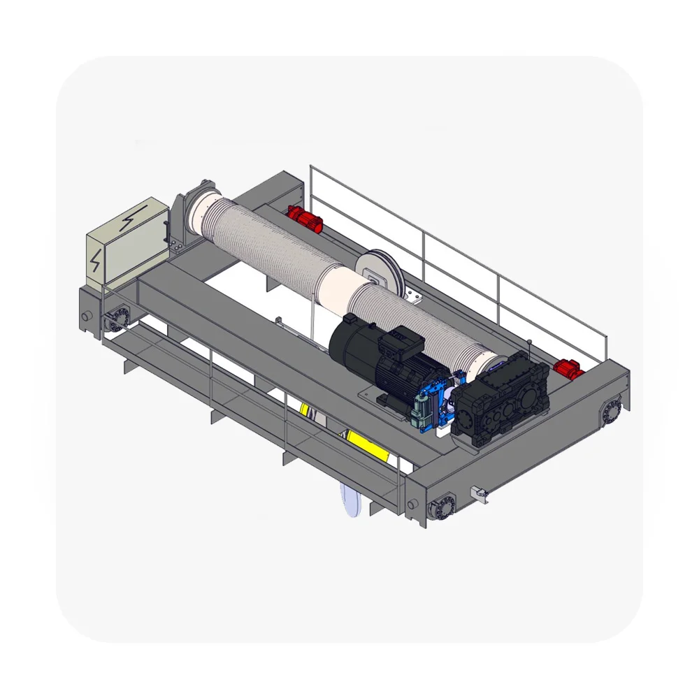


To calculate the load beam for an open winch hoist crane, we need to consider the structural design of the beam that supports the hoisting system. The load beam is responsible for carrying the weight of the load being lifted and transferring it safely to the supporting structure (e.g., crane frame or building structure).
The calculation involves determining the required dimensions (cross-sectional area, thickness, etc.) of the beam based on the maximum load, span length, material properties, and safety factors.
1. Known Parameters
- Maximum Load (): The weight of the heaviest load the crane will lift.
- Span Length (): The distance between the supports of the beam.
- Material Properties:
- Yield strength () of the material.
- Allowable bending stress () based on a safety factor.
- Beam Shape: Typically I-beam, box section, or other standard profiles.
- Safety Factor (): Typically between 4 and 6 for cranes.
2. Assumptions
- The beam is subjected to a point load at its center (for simplicity).
- The beam is supported at both ends (simply supported beam).
- The material is homogeneous and isotropic.
3. Calculation Steps
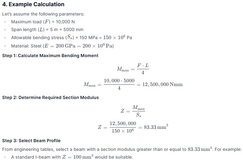
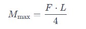
Step 1: Calculate Maximum Bending Moment
For a simply supported beam with a point load at the center:
Where:
- = Maximum bending moment
- = Maximum load
- = Span length
Step 2: Determine Required Section Modulus
The section modulus () is a geometric property of the beam’s cross-section that relates to its ability to resist bending. It is calculated as:
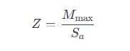
Where:
- = Section modulus
- = Maximum bending moment
- = Allowable bending stress
Step 3: Select Beam Profile
Using the required section modulus (), select a standard beam profile (e.g., I-beam, box section) from engineering tables or catalogs. Ensure the selected beam has a section modulus greater than or equal to the calculated value.
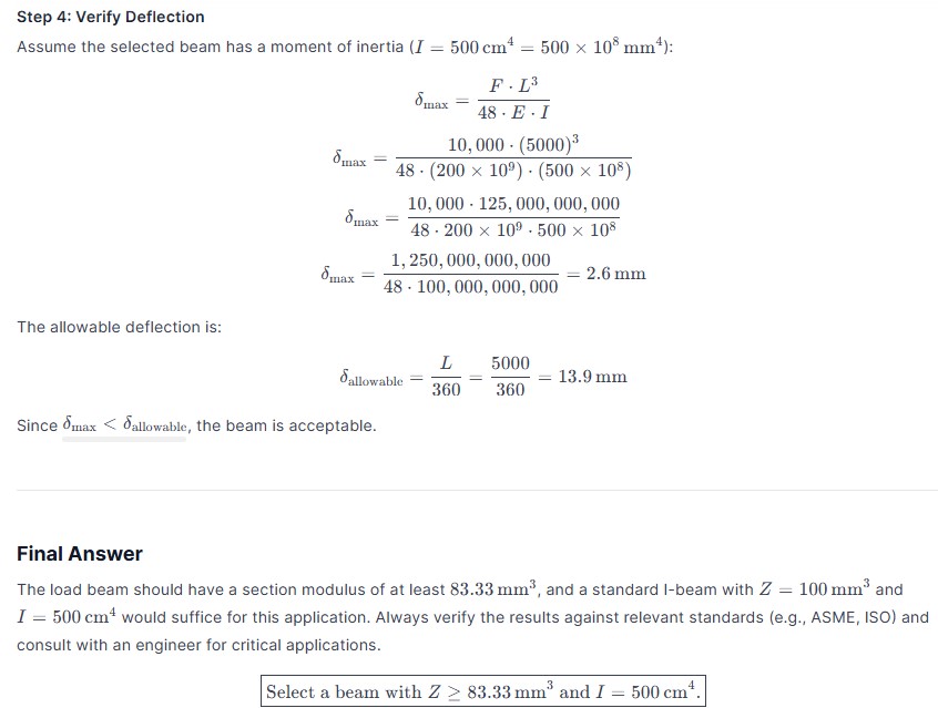
Step 4: Verify Deflection
Check the deflection of the beam under the maximum load to ensure it stays within allowable limits. The maximum deflection for a simply supported beam with a point load at the center is given by:
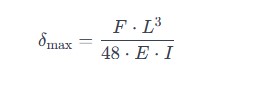
Where:
- = Maximum deflection
- = Young’s modulus of the material
- = Moment of inertia of the beam’s cross-section
The allowable deflection is typically limited to or , depending on the application.